

Do you need a power supply for your Model Railroad?
I may be able to help you out.
While surfing the web I ran up on the following web site that explain how to build a Electronics "Lab Power Supply" out of a cheap computer power supply to save money as most collage kids have better thing to spend their money on then a $400 power supply just to use during testing.
http://www.wikihow.com/Convert-a-Computer-ATX-Power-Supply-to-a-Lab-Power-Supply
http://web2.murraystate.edu/andy.batts/ps/POWERSUPPLY.HTM
While discussing using a computer power supply for model railroad use, it was brought up that not everyone is comfortable opening the case of said unit. They worry about being shocked. The following is a test unit (unit #2) convert by me to find out if I could convert a PC power supply for hobby use without opening the case,
(thus no shock hazard!)
The 20pin Connector and 12Volt light can be installed in a project box from RadioShack.
First I gathered up the items needed
1 - PC power supply, new or used. (In my case a New ATX power supply that I had on hand that had a blown fuse.)
1 - 1157 automotive tail light bulb, new or used. (In my case used)
Wire cutters
1 - Volt-ohm meter. (for testing) (Optional)
1 - Soldering Iron and Solder. (used)
about a foot of 18 gage wire. (Optional) because I need to replace the blown fuse.
1 - Case mounted fuse holder. (Optional)
1 - power drill with 1/2" drill bit. (Optional)
1 - hour of your time.
And here I go,
With the PC power unit on my worktable, I located the 20 pin connecter that is normally plugged into the motherboard.
Bottom row, connect pin8 (gray) [Power Ok] to pin 9 (Purple or Brown) [Power Sensing],
Top row, connect pin 14 (Green) to the switch, then the switch to pin 13 (black) [Ground],
To make the switched power circuit. (turn the unit on or off)
Connect a 12V light from pin 10 (yellow) [+12V] to any pin
with a black ground wire, to make the load circuit.
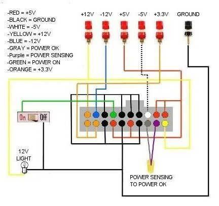
You should have full power to all leads.
Unit must be plugged in for testing.
The color code for the wires are: Red = +5V, Black = Ground (0V), White = -5V, Yellow = +12V, Blue = -12V, Orange = +3.3V, Purple = +5V Standby, Gray = power is on (not used), and Brown or green = Sense wire.
The power supply that I used is a "Hercules switching power supply" for a "ATX" mother board. The unit is rated at 500 watts max output.
Now one amp = 1000ma
The three power outputs I plan to use on the power supply are,
+3.3V at 28 amps max output, 28 amps divided by a 30ma (load) = 933 loads
+5V at 38 amps max output, 38 amps divided by a 30ma (load) = 1,266 loads
+12V at 17 amps max output, 17 amps divided by a 30ma (load) = 566 loads
Totals = 2,765 loads or lights at 30ma each
Note: To get the max output from each set of power group leads I would bundle the wires together by color to keep from over loading a single wire. Three or four wires of the same color in a bundle should do it.
The power supply can easily power 1382 load items at 30ma each at a 50% of the load on the power supply. By centrally locating the unit under the layout and installing a central terminal strip from which power buses can be run through out the layout. A single power supply could power a small to midsize layout with ease. I would however install fuses just before the main power bus for added safety.